Your cart
There are no more items in your cart
- Marián Hubinský
- Technologies
- 3378 views


")
")


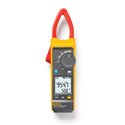
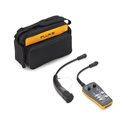
Fluke 393 FC - CAT III 1500 V...
€956.40
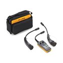
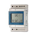
Fluke FEV300/TY1-TY2 - test adapter...
€1,318.80
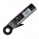
Fluke FEV300/TY2 - test adapter for...
€1,150.80

Related products


- In stock


- In stock


- In stock