Specifications apply at 18°C to 28°C after 30 minutes warm up, at maximum output into 50Ω.
ARBITRARY WAVEFORMS Waveform Parameters
| |
TGA124x |
TGA1210x |
| Waveform Memory: |
64k points/ch |
1M points/ch |
| Waveform Length: |
4 to 65,536 points |
8 to 1,048,576 points |
| Vertical Resolution: |
12 bits (4096 levels) |
| Sample Clock Rate: |
0.1Hz to 40MHz |
0.1Hz to 100MHz (1) |
| Clock Resolution: |
4 digits |
8 digits |
| Clock Accuracy: |
<10 ppm for 1 year (± 1 digit of setting) |
| Clock Temp. Stability: |
Typically <1 ppm/°C |
| Waveform Storage: |
256K Words
Non-volatile RAM |
CF Memory Cards
(32MB to 1GB size) |
| Max. Waveforms: |
100 |
500 per card |
| Note 1: TGA1210x generators can also use an external sample clock, DC to 50MHz. |
Waveform Creation and Editing
| Internal: |
Basic arbitrary waveform creation and editing tools are built into the instrument. Arbitrary waveforms can be built-up using insertion of standard waveforms between points, point by point value setting, and straight line drawing between points. |
| External: |
All TGA1200 series units are supplied with Waveform Manager Plus software for Windows which provides full waveform
creation, editing and management. Waveforms are transferred using the digital interfaces or memory card. |
Sequence
| A number of waveforms can be linked and played as a sequence. Each waveform can have a loop count of up to 32,768. A sequence of waveforms can be looped up to 1,048,575 times or run continuously. |
| |
TGA124x |
TGA1210x |
| Max. Waveforms in a Sequence: |
16 |
1024 |
Output Filter
The output filter type is selectable. This can be used to optimise a particular
waveshape. |
| |
TGA124x |
TGA1210x |
| Filter Choice: |
16MHz Elliptic, 10MHz Elliptic,
10MHz Bessel or None |
40MHz Elliptic,
20MHz Bessel or None |
STANDARD WAVEFORMS Sine, square, triangle, DC, positive ramp, negative ramp, sin(x)/x, pulse, pulse train, cosine, haversine and havercosine.
All Waveforms
| |
TGA124x |
TGA1210x |
| Frequency Accuracy: |
<10 ppm for 1 year |
| Temp. Stability: |
Typically <1 ppm/°C |
| Output Level: |
2.5mV to 10Vpp into 50Ω (5mV to 20Vpp e.m.f.) |
Sine, Cosine, Haversine, Havercosine
| |
TGA124x |
TGA1210x |
| Frequency Range: |
0·1mHz to 16 MHz |
0·1mHz to 40 MHz |
| Freq. Resolution: |
0·1mHz or 7 digits |
0·1mHz or 10 digits |
| Harmonic Distortion: |
<0.1% THD to 100kHz;
<–65dBc to 20kHz,
<–50dBc to 300kHz,
<-35dBc to 10MHz
<-30dBc to 16MHz |
<0.15% THD to 100kHz;
<-60dBc to 20kHz,
<-50dBc to 1MHz,
<-40dBc to 10MHz,
<-30dBc to 40MHz. |
| Nonharmonic Spurii: |
<–65dBc to 1MHz,
<–65dBc + 6dB/octave
1MHz to 16MHz |
<-60dBc to 1MHz,
<-60dBc + 6dB/octave
1MHz to 40MHz. |
Square
| |
TGA124x |
TGA1210x |
| Frequency Range: |
1mHz to 16 MHz |
1mHz to 50 MHz |
| Freq. Resolution: |
1mHz or 4 digits |
1mHz or 8 digits |
| Freq. Accuracy: |
± 1 digit of setting |
| Rise and Fall Times: |
<25ns |
<8ns |
Pulse and Pulse Train
| |
TGA124x |
TGA1210x |
| Period Range: |
100ns to 100s |
40ns to 100s |
| Period Resolution: |
4 digits |
8 digits |
| Period Accuracy: |
± 1 digit of setting |
| Delay Range: |
-99·99s to + 99·99s |
| Delay Resolution: |
0·002% of period
(25ns minimum) |
0.001% of period
(10ns minimum) |
| Width Range: |
25ns to + 99·99s |
10ns to + 99·99s |
| Width Resolution: |
0·002% of period
(25ns minimum) |
0.001% of period
(10ns minimum) |
| Rise and Fall Times: |
<25ns |
<8ns |
Note that the pulse width and absolute value of the delay may not exceed the pulse period at any time.
Pulse trains of up to 10 pulses may be specified, each pulse having independently defined width, delay and level. The baseline voltage is separately defined and the sequence repetition rate is set by the pulse train period. |
Triangle
| |
TGA124x |
TGA1210x |
| Frequency Range: |
0.1mHz to 100kHz |
0.1mHz to 500kHz |
| Freq. Resolution: |
0.1mHz or 7 digits |
0.1mHz or 10 digits |
| Linearity Error: |
<0.1% to 30 kHz |
Ramps and Sin(x)/x
| |
TGA124x |
TGA1210x |
| Frequency Range: |
0.1mHz to 100kHz |
0.1mHz to 500kHz |
| Freq. Resolution: |
0.1mHz or 7 digits |
0.1mHz or 10 digits |
| Linearity Error: |
<0.1% to 30 kHz |
Noise Function (TGA1210x only):
| Digital noise generated by a 35-bit linear feedback register clocked at 100MHz. User’s external filter defines bandwidth and response. |
OPERATING MODES Continuous Waveform runs continuously.
Triggered Burst Each active edge of the trigger signal will produce one burst of the waveform.
| |
TGA124x |
TGA1210x |
| Carrier Waveforms: |
All standard and arbitrary waveforms |
Max. Carrier
Frequency: |
1MHz or the maximum for the selected waveform if lower.
40Msamples/s for ARB and Sequence. |
2.5MHz or the maximum for the selected waveform if
lower. 100Msamples/s for ARB and Sequence. |
| Number of Cycles: |
1 to 1,048,575 |
| Trigger Repetition: |
0.005Hz to 100kHz internal, dc to 1MHz external. |
Trigger Signal
Source: |
Internal from keyboard, previous channel, next channel or trigger generator. External from TRIG IN or remote interface. |
Trigger Start/Stop
Phase: |
± 360° settable with 0.1° resolution, subject to waveform frequency and type. |
Gated Waveform will run while the Gate signal is true and stop while false.
| |
TGA124x |
TGA1210x |
| Carrier Waveforms: |
All standard and arbitrary waveforms |
Max. Carrier
Frequency: |
1MHz or the maximum for the selected waveform
if lower. 40Msamples/s for ARB and Sequence. |
2.5MHz or the maximum for the selected waveform if lower.
100Msamples/s for ARB and Sequence. |
| Number of Cycles: |
1 to 1,048,575 |
| Trigger Repetition: |
0.005Hz to 100kHz internal, dc to 1MHz external. |
| Gate Signal Source: |
Internal from keyboard, previous channel, next channel or trigger generator.
External from TRIG IN or remote interface. |
Gate Start/Stop
Phase: |
± 360° settable with 0.1° resolution, subject to waveform frequency and type. |
Sweep
| Frequency sweep capability is provided for both standard and arbitrary waveforms. Arbitrary waveforms are expanded or condensed to exactly 4096 points and DDS techniques are used to perform the sweep. |
| |
TGA124x |
TGA1210x |
| Carrier Waveforms: |
All standard and arbitrary except pulse, pulse train and sequence. |
| Sweep Mode: |
Linear or logarithmic, triggered or continuous. |
| Sweep Direction: |
Up, down, up/down or down/up. |
| Sweep Range: |
From 1mHz to 16 MHz in one range. |
From 1mHz to 40 MHz in one range. |
| Sweep Time: |
30ms to 999s |
1ms to 999s |
| Marker: |
Variable during sweep. |
| Sweep Trigger Source: |
The sweep may be free run or triggered from the following: Manually from keyboard.
Externally from TRIG IN input or remote interface. |
| Sweep Hold: |
Sweep can be held / restarted by the HOLD key. |
Multi Channel Sweep (multi-channel units only)
| Any number of channels may be swept simultaneously. Amplitude, Offset and Waveform can be set independently for each channel. For TGA124x units the sweep parameters will be the same for all channels. For TGA1210x units the sweep parameters can be set independently for each channel. |
Tone Switching
| Capability provided for both standard and arbitrary waveforms. Arbitrary waveforms are expanded or condensed to exactly 4096 points and DDS techniques are used to allow instantaneous frequency switching. |
| |
TGA124x |
TGA1210x |
| Carrier Waveforms: |
All except pulse, pulse train and sequence. |
| Frequency List: |
Up to 16 frequencies from 1mHz to 10MHz. |
Up to 16 frequencies from 1mHz to 40MHz. |
Trigger Repetition
Rate: |
0.005Hz to 100kHz internal. dc to 1MHz external. Usable repetition rate and waveform frequency depend on the tone switching mode. |
| Trigger Source: |
Internal from keyboard, previous channel, next channel or trigger generator. External from TRIG IN or remote interface. |
| Tone Switching Modes: |
Gated, Triggered or FSK (see below). |
| Tone Switching Modes: |
| Gated: The tone is output while the trigger signal is true and stopped, at the end of the current waveform cycle, while the trigger signal is false. The next tone is output when the trigger signal is true again. |
| Triggered: The tone is output when the trigger signal goes true and the next tone is output, at the end of the current waveform cycle, when the trigger signal goes true again. |
| FSK: The tone is output when the trigger signal goes true and the next tone is output, immediately, when the trigger signal goes true again. Using 2 channels with their outputssummedtogether it is possible to generateDTMFtest signals. |
Trigger Generator
| Internal source 0.005 Hz to 100kHz square wave adjustable in 10us steps. 3 digit resolution. Available for external use from any SYNC OUT socket. |
OUTPUTS Main Output - One for each channel
| |
TGA124x |
TGA1210x |
| Output Impedance: |
50Ω |
| Amplitude Range: |
5mV to 20Vpp open circuit (2.5mV to 10Vpp into 50Ω). Amplitude can be specified open circuit
(hi Z) or into an assumed load of 50Ω or 600Ω in Vpk-pk, Vrms or dBm. |
| Amplitude Accuracy: |
2% ±1mV at 1kHz into 50Ω. |
| Amplitude Flatness: |
±0.2dB to 200 kHz;
±1dB to 10 MHz;
±2.5dB to 16 MHz. |
±0.2dB to 1 MHz;
±0.4dB to 40 MHz; |
| DC Offset Range: |
±10V from 50Ω.
Offset plus signal peak limited to ±10V. |
| DC Offset Accuracy: |
Typically 3% ±10mV, unattenuated. |
| Resolution: |
3 digits or 1mV for both Amplitude and DC Offset. |
Auxiliary Sine Output
| TGA124x |
TGA12101 |
TGA12102/104 |
| N/A |
N/A |
Nominal 1Vp-p sinewave, frequency set by system clock, frequency 0.1Hz to 50MHz. |
ARB Clock Out
| See ARB clock In/Out within INPUTS section. |
Sync Out - One for each channel
| Multifunction output user definable or automatically selected to be any of the following: |
| |
TGA124x |
TGA1210x |
Waveform Sync:
(all waveforms) |
Square wave with 50% duty cycle at the main waveform frequency, or pulse coincident with the first few points of an arbitrary waveform. |
Position Markers:
(Arbitrary only) |
Any point(s) on the waveform may have associated marker bit(s) set high or low. |
| Burst Done: |
Produces a pulse coincident with the last cycle of a burst. |
| Sequence Sync: |
Produces a pulse coincident with the end of a waveform sequence. |
| Trigger: |
Selects the current trigger signal. Useful for synchronizing burst or gated signals. |
| Sweep Sync: |
Outputs a pulse at the start of sweep to synchronize an oscilloscope or recorder. |
| Sweep Marker: |
N/A |
Additional pulse for use as sweep marker. |
| Phase Lock Out: |
Used to phase lock two generators. Produces a positive edge at the 0° phase point. |
| Signal Level: |
Logic levels of <0.8V and >3V for all outputs. |
Logic levels of <0.8V and >3V for all outputs except Sweep Sync. |
Signal Level:
(Sweep Sync.only) |
N/A |
3 level waveform - as above but plus narrow +1V pulse at marker. |
Cursor/Marker Out (TGA124x units only)
| Adjustable output pulse for use as a marker in sweep mode or as a cursor in arbitrary waveform editing mode. Can be used to modulate the Z axis of an oscilloscope or be displayed on a second ‘scope channel. |
| |
TGA124x |
TGA1210x |
| Signal Level: |
Adjustable from nominally 2V to 14V, normal or inverted; adjustable width as a cursor. |
N/A |
| Output Impedance: |
600Ω typical |
N/A |
INPUTS Trig In
| |
TGA124x |
TGA1210x |
| Frequency Range: |
DC to 1MHz. |
| Signal Range: |
Threshold nominally TTL level;
maximum input ±10V. |
Threshold adjustable over ±5V range;
maximum input ±10V. |
| Min. Pulse Width: |
50ns, for Trigger/Gate; 50us for Sweep mode. |
| Polarity: |
Selectable as high/rising edge or low/falling edge. |
| Input Impedance: |
Typically 10 kΩ. |
Modulation In
| |
TGA124x |
TGA1210x |
| Frequency Range: |
DC to 100kHz. |
DC to 100kHz. |
| VCA Signal Range: |
Approximately 1V pk-pk for 100% level change at maximum output. |
| SCM Signal Range: |
Approximately ± 1Vpk for maximum output. |
| Input Impedance: |
Typically 1 kΩ. |
Sum In
| |
TGA124x |
TGA12101 |
TGA12102/4 |
| Frequency Range: |
DC to 8MHz. |
DC to 30MHz. |
DC to 16MHz |
| Signal Range: |
Approximately 2 Vpk-pk input for 20Vpk-pk output. |
| Input Impedance: |
Typically 1 kΩ. |
Hold
| Holds an arbitrary waveform at its current position.ATTL low level or switch closure causes the waveform to stop at the current position and wait until a TTL high level or switch opening which allows the waveform to continue. The front panel MAN HOLD key or remote command may also be used to control the Hold function. While held the front panel MAN TRIG key or remote command may be used to return the waveform to the start. The Hold input may be enabled independently for each channel. Input impedance is10kΩ. |
Ref Clock In/Out
| |
TGA124x |
TGA1210x |
| Set to Input: |
Input for an external 10MHz reference clock. TTL/CMOS threshold level. |
| Set to Output: |
Buffered version of the internal 10MHz clock. Output levels nominally 1V and 4V from 50Ω. |
| Set to Phase Lock: |
Used together with SYNC OUT on a master and TRIG IN on a slave to synchronise (phase lock)
two separate generators. |
ARB Clock In/Out
| TGA1210x generators can use an external signal as the arbitrary waveform clock. The TGA12102 and TGA12104 also include an internal system clock generator (in addition to the individual channel clock generators). The output of this system clock can be made available to drive external circuitry or the input of another generator. |
| |
TGA124x |
TGA12101 |
TGA12102/4 |
| Set to Input: |
N/A |
Input for an external Arb clock. TTL/CMOS threshold level. |
| Set to Output: |
N/A |
N/A |
Outputs System Clock, logic level <0.8V to >3V |
| Frequency Range: |
N/A |
DC to 50MHz. |
| Max. Input Voltage: |
N/A |
+5V, -1V. |
MULTI-CHANNEL OPERATION Channel Relationships:
| The channels of a multi-channel unit can be operated entirely independently, as if they were separate generators. The "copy" key allows the settings of any channel to be instantly copied to another when required. Alternatively, inter-channel relationships of modulation, summing, triggering, or phase locking can be set up. |
System Clock: (TGA12102/12104 only)
The TGA12102/12104 units incorporate an additional frequency generator which can be used as a clock source for multi-channel arbitrary waveforms and as an auxiliary output.
|
| |
TGA124x |
TGA12101 |
TGA12102/104 |
| Frequency Range: |
N/A |
N/A |
DC to 50MHz. |
| Frequency Resolution: |
N/A |
N/A |
0·1Hz |
The output of the system clock is available as a 1 volt pk-pk sinewave at the Auxiliary Sine Out socket, and as a logic level squarewave at the Ext. ARB In/Out socket.
When not being used as a clock source for multi-channel arbitrary waveforms, the system clock provides an independent fixed amplitude sine or square output which is additional to the two or four main channel outputs. |
Inter-channel Modulation:
| The waveform from any channel may be used to Amplitude Modulate (AM) or Suppressed Carrier Modulate (SCM) the next channel. Alternatively any number of channelsmaybe Modulated (AM orSCM)with the signal at theMODULATION input socket. |
| |
TGA1242/1244/12102/12104 |
| Carrier frequency: |
Entire range for selected waveform. |
| Carrier waveforms: |
All standard and arbitrary waveforms. |
| Modulation Types: |
AM: Double sideband with carrier.
SCM: Double sideband suppressed carrier. |
| Modulation source: |
Internal from the previous channel. External from Modulation input socket. The external modulation signal may be applied to any number of channels simultaneously. |
| Frequency Range: |
DC to >100 kHz. |
| Internal AM Depth: |
0% to 105%. |
| Internal AM Resolution: |
1% |
Carrier Suppression
(SCM): |
> 40dB. |
External Modulation
Signal Range: |
VCA: Approximately 1V pk-pk for 100% level change at maximum output.
SCM: Approximately ± 1Vpk for max. output. |
Multi Channel Sweep
Any number of channels may be swept simultaneously. Amplitude, Offset and Waveform can be set independently for each channel.
For TGA124x units the sweep parameters will be the same for all channels.
For TGA1210x units the sweep parameters can be set independently for each channel.
|
Inter-channel Analogue Summing:
Waveform Summing sums the waveform from any channel into the next channel.
Alternatively any number of channels may be summed with the signal at the SUM input socket. |
| |
TGA1242/1244 |
TGA12102/104 |
| Carrier frequency: |
Entire range for selected waveform. |
| Carrier waveforms: |
All standard and arbitrary waveforms. |
| Sum source: |
Internal from the previous channel. External from SUM IN socket. |
| Frequency Range: |
DC to >8MHz. |
DC to >16MHz. |
| External Signal Range: |
Approx. 5Vpk-pk input for 20Vpk-pk output. |
Approx. 2Vpk-pk input for 20Vpk-pk output. |
| Input Impedance: |
Typically 1 k |
Inter-channel Phase locking:
Two or more channels may be phase locked together. Each locked channel may be assigned a phase angle relative to the other locked channels. With one channel assigned as the Master and other channels as Slaves, a frequency change on the master will be repeated on each slave thus allowing multiphase waveforms at the same frequency to be easily generated.
The signals from the REF IN/OUT socket and the SYNC OUT socket can be used to phase lock two instruments where more than 4 channels are required.
Different condition apply to Standard waveforms generated using DDS techniques (sine, cosine, haversine, havercosine, triangle, ramps and sinex/x), and those generated using variable clock arbitrary waveform techniques which include square, pulse and pulse train.
Arbitrary waveforms and waveform sequences may be phase locked to the Master channel, but certain constraints apply to waveform lengths and clock frequency ratios.
On the TGA12102/12104, arbitrary waveforms and waveform sequences can alternatively be clocked from a separate internal clock generator (System clock), or from an external clock input (external ARB clock).
When using these clock sources, the restrictions that apply when using the Master channel as the clock source are eliminated. In addition, frequency changes require no settling time to re-establish phase locking, and thus phase continuous frequency changing or sweeping is possible. |
| |
TGA1242/1244 |
TGA12102/104 |
Phase Resolution:
(DDS waveforms) |
0.1 degree. |
Phase Resolution:
(Non DDS waveforms) |
0.1 degree or 360 degrees/number of points. |
| Clock Source: |
Master Channel. |
Master Channel, System Clock or Ext. ARB clock |
| Phase Error: |
<±10ns. |
<±5ns (internal clock)
<+/-2ns (external ARB or system clock). |
| N.B. DDS waveforms are Sine, Cosine, Haversine, Havercosine, Triangle, Ramps and Sin(x)/x. Non DDS waveforms are Pulse, Pulse Train, and all Arbitrary waveforms. |
GENERAL
| |
TGA124x |
TGA1210x |
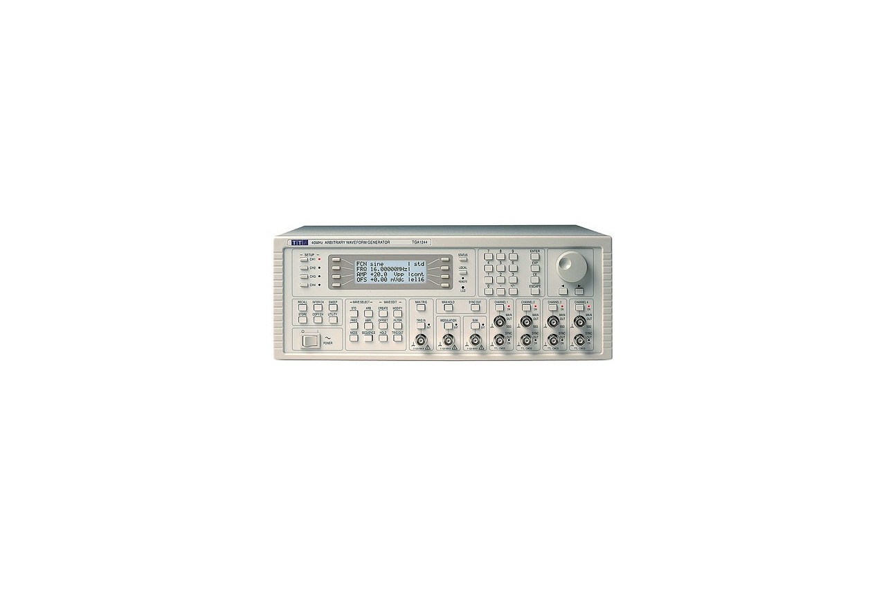
| Display: |
20 character x 4 row alphanumeric LCD. |
| Data Entry: |
Keyboard selection of mode, wave etc., value entry direct by numeric keys or by rotary control. |
| Memory Card: |
N/A |
Removable card slot conforming to the Compact Flash standard.
Sizes 32MB to 1GB. |
Waveform Storage:
(non volatile) |
Up to 100 waveforms within 256K words. |
Up to 500 waveforms per CF card. |
| Stored Settings: |
Up to 9 full set-ups. |
Up to 500 full set-ups per CF card. |
MECHANICAL, POWER, COMPLIANCE
TGA:
|
1241 |
12101 |
1242 |
12102 |
1244 |
12104 |
| Width |
212mm (½ rack) |
350mm |
| Height: |
130mm (3U) |
130mm (3U) |
| Length: |
335mm |
335mm |
| Weight: |
4.1 kg |
4.2kg |
7.1kg |
5.9kg |
7.2kg |
6.0kg |
| Power: |
A |
B |
A |
C |
A |
C |
A = 230V, 115V or 100V ±14%, 50/60Hz, adjustable internally
B = 230V, 115V or 100V ±14%, 50/60/400Hz, adjustable internally
C =100V to 230V ±14%, 50/60/400Hz, universal input |
| Maximum VA: |
A |
B |
A |
C |
A |
C |
| Temperature: |
Operating Range +5°C to 40°C, 20-80% RH
Storage Range -20°C to + 60°C. |
| Environmental: |
Indoor use at altitudes to 2000m, Pollution Degree 2 |
| Safety: |
Complies with EN61010-1. |
| EMC: |
Complies with EN61326. |