Váš nákupný košík
Vo vašom košíku nie sú žiadne ďalšie položky.


Aim-TTi products are using TCP port 9221.
Use command: edcmde-i386 /aimtti /ip 192.168.1.21 /cmd V1o?;I2o?;V2o?;I2o?;V3o?;I3o?; to read actual voltage and current from all outputs. Connection is to IP address 192.168.1.21, port 9221.
Commands must be sent as specified in the commands list and must be terminated with the command terminator code 0AH (Line Feed, LF) except for commands over the TCP socket where the terminator is allowed but not required. Commands may be sent in groups with individual commands separated from each other by the code 3BH (;). The group must be terminated with command terminator 0AH (Line Feed, LF).
Responses from the instrument to the controller are sent as specified in the commands list. Each response is terminated by a <RESPONSE MESSAGE TERMINATOR> which is 0DH (Carriage Return, CR) followed by 0AH (Line Feed, LF).
<WHITE SPACE> is defined as character codes 00H to 20H and is ignored except in command identifiers. e.g. ‘*C LS’ is not equivalent to ‘*CLS’.
The high bit of all characters is ignored. The commands are case insensitive
A separate error and status model is maintained for each interface instance; an interface instance is defined as a potential connection. USB, RS232 and GPIB are inherently single connections so represent one interface instance each. LAN, however, allows for multiple simultaneous connections so represents multiple interface instances. Two interface instances are allocated to the two TCP socket interfaces and one more is allocated to the Web page interface. Having a separate model for each interface instance ensures that data does not get lost as many commands e.g. ‘*ESR?’ clear the contents on read.
Error status is maintained using a set of registers as shown below.

The Event Status Register is read and cleared by the ‘*ESR?’ command.
It is a bit field where each bit has the following significance.
| bit 7 | Power On. Set when power is first applied to the instrument. |
| bit 6 | User Request (Not used). |
| bit 5 | Command Error. Set when a syntax type error is detected in a command from the bus. The parser is reset and parsing continues at the next byte in the input stream |
| bit 4 | Execution Error. Set when an error is encountered while attempting to execute a completely parsed command. The appropriate error number will be reported in the Execution Error Register, see Error Messages section |
| bit 3 | Verify Timeout Error. Set when a parameter is set with ‘verify’ specified and the value is not reached within 5 seconds, e.g. output voltage is slowed by a large capacitor on the output. |
| bit 2 | Query Error. This bit is set when a query error occors over GPIB. Query Errors are not possible on the other interfaces. When this happerns the approprate error number will be reported in the Query Error Register as listed below. 1. Interrupted error. 2. Deadlock error. 3. Unterminated error. |
| bit 1 | Not used. |
| bit 0 | Operation Complete: Set in response to the ‘*OPC’ command. |
There are two Limit Event Status Registers; These are read and cleared using ‘LSR1?’ and ‘LSR2’ respectively. On power up these registers are set to 0 then immediately set to show new limit status.
| bit 7 | Reserved for future use |
| bit 6 | Set when a trip has occurred that can only be reset from the front panel or by removing and reapplying the AC power |
| bit 5 | Set when output sense trip has occurred |
| bit 4 | Set when over current trip has occurred |
| bit 3 | Set when over voltage trip has occurred |
| bit 2 | Set when output enters power limit |
| bit 1 | Set when output enters current limit (CI mode) |
| bit 0 | Set when output enters voltage limit (CV mode) |
This register contains a number representing the last error encountered over the current interface. The Execution Error register is read and cleared using the ‘EER?’ command. On power up this register is set to 0 for all interface instances.
Error messages defined to date are.
| 0 | No error encountered |
| 1 - 9 | Internal hardware error detected. |
| 100 | Range error. The numeric value sent is not allowed. For example “V1 70” when in the 60V range “V1 100” ever or “V1 50” when outputs are linked and V2 is set to 200% of V1. |
| 101 | A recall of set up data has been requested but the store specified contains corrupted data. This indicates either a hardware fault or a temporary data corruption, which can be corrected by writing data to the store again. |
| 102 | A recall of set up data has been requested but the store specified does not contain any data. |
| 103 | Command invalid. The command is recognised but not valid in the current circumstances. Typical examples would be trying to change V2 directly while in linked mode or changing the ratio when outputs are not linked. This error is also generated when tryint to select Ratio Tracking mode if eithyer output is set below 1V or trying to select mode 3 or mode 4 when either output is switched on. |
| 200 | Read Only: An attempt has been made to change the settings of the unit from an instrument without write privileges. See ‘Interface locking’ below for detail. |
This register is of limited use when the interface being used is not GPIB.
This register controls which bits of the Status byte register form the ist local message: If the result of bitwise ANDing The Status Bye Register with this register is zero then the value of ist is 0 otherwise it is 1.
All interfaces are live at all times; this removes the need to select the active interface and is also a LXI requirement. To reduce the risk of the instrument being inadvertently under the control of two interfaces at once a simple lock and release mechanism is provided in the instruction set. The lock is automatically released where it is possible to detect disconnection and when the local button is pressed. Access to the interfaces may also be limited using the web page.
Any interface may request to have exclusive control of the interface by sending a ‘IFLOCK’ command. The lock may only be released by the interface instance that has the lock by sending an ‘IFUNLOCK’ command and may be queried by sending a ‘IFLOCK?’ command. The reply for any of these commands will be ‘-1’ if the lock is owned by another interface instance, ‘0’ if the interface is free and ‘1’ if the lock is owned by the requesting interface instance. Sending any command that changes the instrument status will set bits 4 and 6 of the Event Status Register and put 200 into the Execution Error Register to indicate that you do not have sufficient privileges for the required action.
Note: it is also possible to configure the maximum privileges for a particular interface to either ‘read only’ or ‘no access’ from the Web page interface.
There are 6 operating modes defined for the unit as listed in the following table. Of which 4 may be selected under digital remote control.
The operating mode can be queried using the ‘CONFIG?’ and set using the ‘CONFIG’ commands
| 0 | Output V2 tracks V1 at a fixed ratio 5% to 2000% The ratio is set on entry to this mode and this mode can only be entered if both V1 and V2 are set to at least 1V. This is the only mode where the ‘RATIO’ and ‘RATIO?’ commands are legal. |
| 1 | Unused This mode is reserved for single output power supplies. |
| 2 | Dual Output Unlinked. In this mode the two outputs are independant of each other. Only in this mode are commands that directly set V2 allowed. i.e. ‘V2’, ‘V2V’, ‘DECV2’, ‘DECV2V’, ‘INCV2’, ‘INCV2V’ and ‘DELTAV2’ |
| 3 | Track voltage and Current (Displaying combined voltage) This mode in intended to be a pseudo series mode. This mode can only be entered when both outputs are off.The ouputs are not connected together internally. It is upto the user to wire the outpus as required. In this mode in is not possible to set V2 or I2 directly. V2 and I2 setpoints will allways match V1 and I1 setpoints. |
| 4 | Track voltage and Current (Displaying combined current) This mode in intended to be a pseudo paralell mode. This mode can only be entered when both outputs are off.The ouputs are not connected together internally. It is upto the user to wire the outpus as required. In this mode in is not possible to set V2 or I2 directly. V2 and I2 setpoints will allways match V1 and I1 setpoints. |
| -1 | Analog control active. This mode can not be set over the interfaces but will be returned if analog control selected. You may query the instrument but any attempt to chage its settings will generate a ‘Read Only’ error as the interfaces have been locked by the analog controls. (see Interface Locking above). |
Note: Entry to modes 3 and 4 is only possible if both ontputs are switched off. On entry output 2 voltage range, voltage set point, current setpoint, OVP limit and OCP limit will be set to match the settings for output 1.
This section lists commands and queries implemented in this instrument. The commands are listed in alphabetical order within the function groups.
There are no dependent parameters, coupled parameters, overlapping commands, expression program data elements or compound command program headers; each command is completely executed before the next command is started.
All commands that send a reply are terminated with the remote message terminator (ASCII 0DH, 0AH carriage return, line feed).
| <nrf> | A number in any format e.g. 12, 12.00, 1.2e1 and 120e-1 are all accepted as the number 12. Any number, when received, is converted to the required precision consistent with the use then rounded to obtain the value of the command. |
| <nr1> | A number with no fractional parts. |
| <nr2> | A number with fixed point format. |
All voltages are in volts and all currents are in amps. For ‘RATIO’ the figure is in percent
The maximum output voltage that can be requested is either 60V volts or 80V depending on the range selected; The minimum is 0V. The limits however may change when operationg in linked mode as for example if outputs are linked with V2 set to 200% of V1 then the allowable range for V1 is now 0 to 30 in low range as otherwise V2 would be set to an illegal value.
When operating in link mode the ratio between the two outputs can be 5% to 2000%.Changing the ratio changes V2. However, this is simlarly limited depending on what V1 is set to. If for example V1 were set to 10V and V2 is operating in the low range 60V. The range for ratio becomes 5 to 600 as otherwise V2 would be set to an illegal value.
The maximum output current that can be requested is either 50A; the minimum is 0.01A
| *CLS | Clear Status. |
| *ESE <nrf> | Set Event Status Enable Register |
| *ESE? | Report value of Event Status Enable Register |
| *ESR? | Query and clear the Event Status Register. The response format is <nr1>. See "Error and Status reporting" for details of the response. |
| *IDN? | Returns the instrument identification. The exact response is determined by the instrument configuration and is of the form: <NAME>,<model>, <serial no.>, <version> where <NAME> is the manufacturer"s name, <model> defines the type of instrument, <serial> is the unit serial number and <version> is the revision level of the software installed. |
| *IST? | Returns the ist Local message as defined by IEE488.2. The response is 0 if the local message is false, 1 if the local message is true. Note: This command is of limited use if the interface is not GPIB. |
| *OPC | Sets the OPC bit (bit 0) in the Event Status Register |
| *OPC? | Query operation complete. Always returns 1 because all commands are sequential. |
| *RST | Resets the instrument to the remote operation default settings with the exception of remote interface settings, stored set-ups and DC state at power-on setting. Default settings are: 0V,1A, DeltaV=10mV, DeltaI=10mA, output off, Meter Average cancelled, VRANGE=1 (0 to 60V), OVP & OCP at instrument maximum and local sense. |
| *SRE <nrf> | Sets Service Request Enable Register |
| *SRE? | Report the value in the Service Request Enable Register |
| *STB? | Report the Value in the Status Byte |
| *PRE <nrf> | Set the Parallel Poll Enable register. |
| *PRE? | Report the value in in the Parallel Poll Enable register. |
| *TRG | There is no trigger capability. This command is accepted but performs no action (ignored). |
| *TST? | Self test. There is no self-test capability so the response is always "0". |
| *WAI | Wait for Operation Complete True. Because all operations are sequential this command does nothing. |
| EER? | Query and clear the Execution Error Register. The response format is <nr1>. See "Error and Status reporting" for details of the response |
| IFLOCK | Request interface "lock". This requests exclusive access control of the instrument. The response is "1" if successful or "-1" if the lock is unavailable either because it is already in use or the user has disabled this interface from taking control using the web interface. |
| IFLOCK? | Query the status of the interface "lock". The return value is "1" if the lock is owned by the requesting interfaced instance; "0" if there is no active lock or "-1" if the lock is unavailable either because it is already in use or the user has disabled this interface from taking control using the web interface. |
| IFUNLOCK | Release the "lock" if possible. This command returns the value "0" if successful. If this command is unsuccessful "-1" is returned, 200 is placed in the Execution Register and bit 4 of the Event Status Register is set indicating that you do not have the authority to release the "lock". |
| LOCAL | Go to Local. This does not release any active interface lock so that it remains with the selected interface when the next remote command is received. Going to Local with this command, or the front panel Local key, will keep the V/I settings at their last remotely set values and will leave the output(s) in their present state. |
| LSE<n> <nrf> | Set the value of the Limit Status Enable Register <n>. |
| LSE<n>? | Report value of limit Status Enable Register <n>. |
| LSR<n>? | Query and clear the Limit Event Status Register <n>. The response format is <nr1>. See "Error and Status reporting" for details of the response |
| QER? | Query and Clear the Query Error Register. The response is <nr1> Note: This command has no meaning if the interface is anything other than GPIB. If the interface is not GPIB the result is allways 0. |
| TRIPRST | Attempts to clear any trip conditions. |
| ADDRESS? | Returns the bus address; this is the address used by GPIB, if fitted, or may be used as a general identifier over the other interfaces. The syntax of the response is <nr1>. |
| CONFIG <nrf> | Sets the configuration of the unit this to <nr1> where <nr1> has the meaning specified in Operating Modes above. |
| CONFIG? | Returns the configuration of the unit as defined in Operating Modes above. |
| DAMPING<n> <nr1> | Set the current meter averaging function of output <n> to <nr1>, where <nr1> has the following meaning: 0 = OFF, 1 = ON. |
| DECI<n> | Decrement output <n> current limit by step size. |
| DECV<n> | Decrement output <n> voltage by step size. |
| DECV<n>V | Decrement output <n> voltage by step size and verify. |
| DELTAI<n> <nrf> | Set the output <n> current step size to <nrf> amps. |
| DELTAI<n>? | Return the output <n> current step size. Response is DELTAI<n> <nr2>, where <nr2> is in amps. |
| DELTAV<n> <nrf> | Set the output <n> voltage step size to <nrf> volts. |
| DELTAV<n>? | Return the output <n> voltage step size. Response is DELTAV<n> <nr2>, where <nr2> is in volts. |
| I<n> <nrf> | Set the output <n> current limit to <nrf>. |
| I<n>? | Return the set current of output <n>. Response is I<n> <nr2>, where <nr2> is in amps. |
| I<n>O? | Return output <n> measured current. Response is <nr2>, where <nr2> is in amps. |
| INCI<n> | Increment output <n> current limit by step size. |
| INCV<n> | Increment output <n> voltage by step size. |
| INCV<n>V | Increment output <n> voltage by step size and verify. |
| LOGICIN<n>? | Returns the state of the LogicIn signal for channel <n> Returns "1" if the input is energised, "0" otherwise. |
| LOGICOUT<n>? | Returns the state of the LogicIn signal for channel <n> Returns "1" if the input is energised, "0" otherwise. |
| OCP<n> <nrf> | Set output <n> over current protection trip point to <nrf> Amps |
| OCP<n>? | Return the current trip setting for output <n>. Response is IP<n> <nr2> where <nr2> is in Amps |
| OP<n> <nrf> | Set output <n> on or off, where <nrf> has the following meaning: 1 = ON, 0 = OFF |
| OP<n>? | Returns output <n> on or off status. Response <nr1> has the following meaning: 1 = ON, 0 = OFF |
| OPALL <nrf> | Set all outputs on or off, where <nrf> has the following meaning: 1 = ON, 0 = OFF |
| OVP<n> <nrf> | Set output <n> over voltage protection trip point to <nrf> Volts |
| OVP<n>? | Return the voltage trip setting for output <n>. Response is VP<n> <nr2> where <nr2> is in Volts |
| RATIO <nrf> | This command is only valid if opeating in mode 0; Voltage Tracking. Sets the ratio of V2 to V1 to <nrf> percent. The allowable range is 5% to 2000% providing this would not set V2 to an illegal value. If output 2 is enabled changing the ratio will immediatley change the output voltage on V2. |
| RATIO? | When opeating in mode 0; Voltage Tracking. Returns <nr2> where <nr2> is the ratio set between V2 and V1 as a percentage. In all other modes returns -1 to indicate that RATIO is not valid in the current mode. |
| RCL<n> <nrf> | Recall output <n> saved setting <nrf>, where <nrf> range is 0 to 9. |
| SAV<n> <nrf> | Stores current settings of output <n> to store <nrf>, where <nrf> range is 0 to 9. |
| SENSE<n> <nrf> | Enables remote sense when <nrf> is 1, disables remote sense when <nrf> is 0. |
| V<n> <nrf> | Set output <n> to <nrf> volts. |
| V<n>? | Return the set voltage of output <n>. Response is V<n> <nr2>, where <nr2> is in volts. |
| V<n>O? | Return output <n> measured voltage. Response is <nr2>V, where <nr2> is in volts. |
| V<n>V <nrf> | Set output <n> to <nrf> volts, with verify. |
| VRANGE<n> <nrf> | Set output <n> to <nrf> voltage range to <nrf>. Where <nrf> is 1 for low range (0 to 60V) and 2 for hight range (0 to 80V). |
| VRANGE<n>? | Report output <n> voltage range. Returns <nr1>. Where <nr1> is 1 for low range (0 to 60V) and 2 for hight range (0 to 80V). |
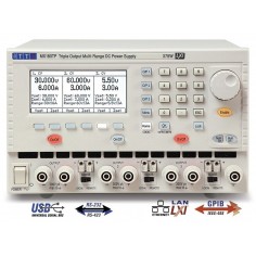
Komunikácia so zdrojom MX100TP.